The Hydraulics Laboratory is a state-of-the art facility used to conduct a variety of experiments pertaining to water. Among other things, this laboratory provides a means of testing the hydraulic properties of submerged bridges and the hydraulic properties of highway drainage structures and stream crossings. The laboratory provides operational engineers with the design tools needed to complete their tasks. For example, engineers have used the facility to solve stream stability problems, develop design standards for bridges in high flood risk areas, and contribute to design standards for scouring around bridge piers and submerged bridge decks.
Common topics of design for hydraulic engineers include hydraulic structures such as dams, levees, water distribution networks including both domestic and fire water supply, distribution and automatic sprinkler systems, water collection networks, sewage collection networks, storm water management, sediment transport, and various other topics related to transportation engineering and geotechnical engineering. Equations developed from the principles of fluid dynamics and fluid mechanics are widely utilized by other engineering disciplines such as mechanical, aeronautical and even traffic engineers.
Related branches include hydrology and rheology while related applications include hydraulic modeling, flood mapping, catchment flood management plans, shoreline management plans, estuarine strategies, coastal protection, and flood alleviation.
For academic purpose the laboratory is used by the Department of Civil Engineering and Department of Mechanical Engineering with average of 12 periods in a week.
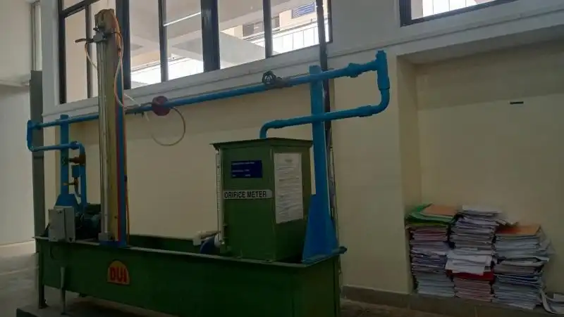
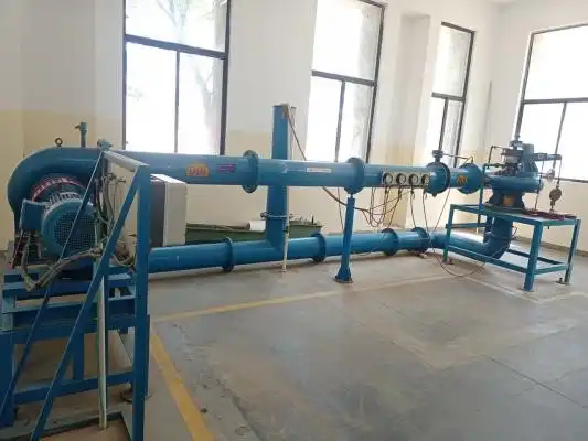
An orifice meter is a conduit and a restriction to create a pressure drop. An hour glass is a form of orifice. A nozzle, venturi or thin sharp edged orifice can be used as the flow restriction. An orifice in a pipeline is shown in figure with a manometer for measuring the drop in pressure (differential) as the fluid passes through the orifice. The minimum cross sectional area of the jet is known as the “vena-contracta.”
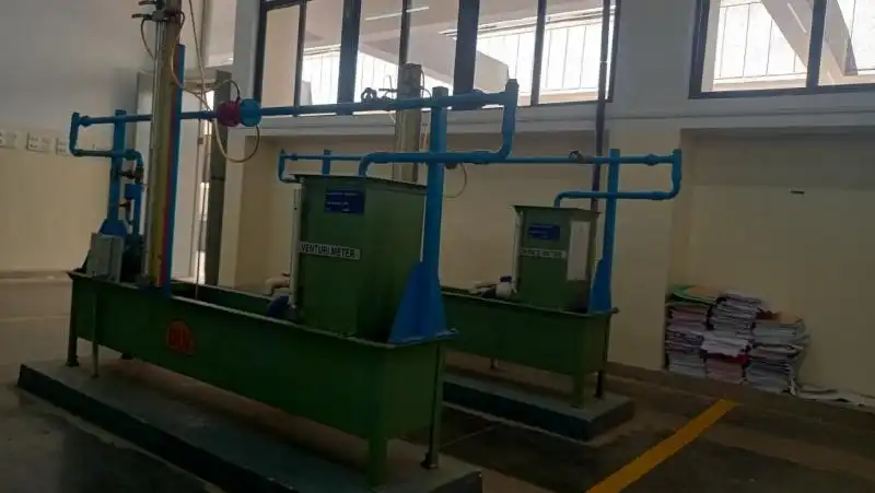
Venturimeter is a flow measurement instrument. Here, a converging section of a pipe is used to increase the flow velocity and a corresponding pressure drop from which the flow rate of the fluid is deduced based on Bernoulli’s equation.
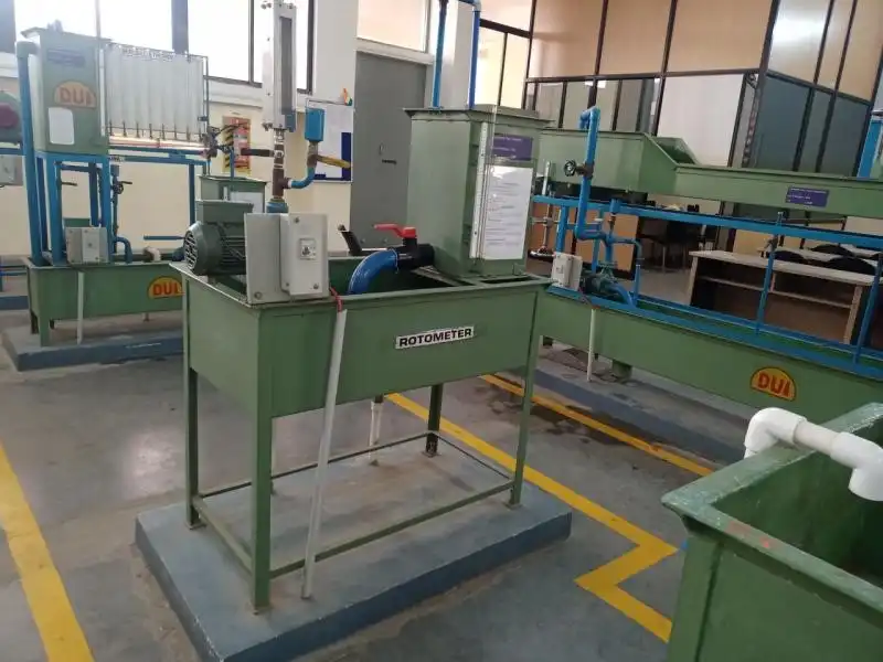
A rotameter is a flow meter device that measures the volumetric flow rate of a gas or fluid. It consists of a tapered tube with a moving internal float. Sometimes known as mechanical flow meters, gravity flow meters or variable area flow meters. The gravity term relates to the fact the rotameter needs to be installed vertically, as the flow rate, is read from the float position in the tapered tube, determined by the balance of forces underneath the float from gravity. The metering tube starts with the smaller taper at the bottom and expands out to the top, with the scale graduations on the tube. With no flow, the float sits at the bottom of the tube, as the fluid flow increases the float begins to rise until an equilibrium is maintained with the viscous forces and gravity.
.webp)
Centrifugal pumps are some of the most commonly used industrial pumps in the world. They are used for a wide variety of applications across a number of industries. However, depending on the task that needs to be accomplished, it may be worth your time and money to invest in a multistage pump over a traditional single-stage centrifugal pump. The primary difference between single-stage and multistage centrifugal pumps lies in the number of stages (also referred to as impellers) they have. As the name implies, single-stage pumps have only one impeller, whereas multistage pumps have at least two.
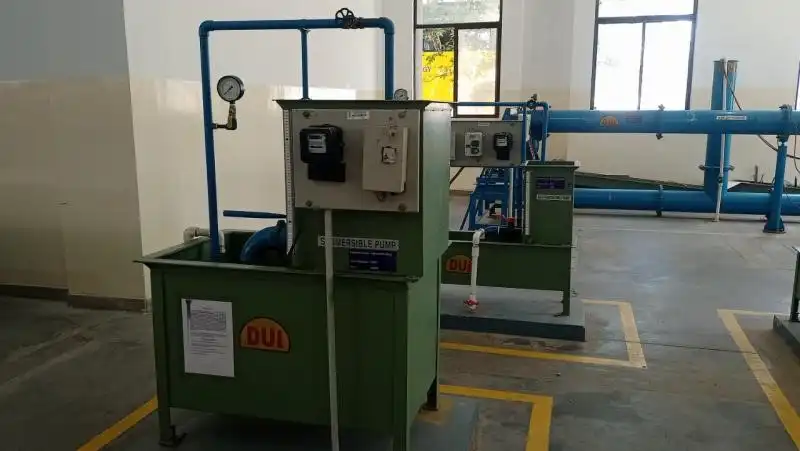
A submersible pump (or electric submersible pump (ESP)) is a device which has a hermetically sealed motor close-coupled to the pump body. The whole assembly is submerged in the fluid to be pumped. The main advantage of this type of pump is that it prevents pump cavitation, a problem associated with a high elevation difference between the pump and the fluid surface. Submersible pumps push fluid to the surface, rather than jet pumps, which create a vacuum and rely upon atmospheric pressure. Submersibles use pressurized fluid from the surface to drive a hydraulic motor down hole, rather than an electric motor, and are used in heavy oil applications with heated water as the motive fluid.
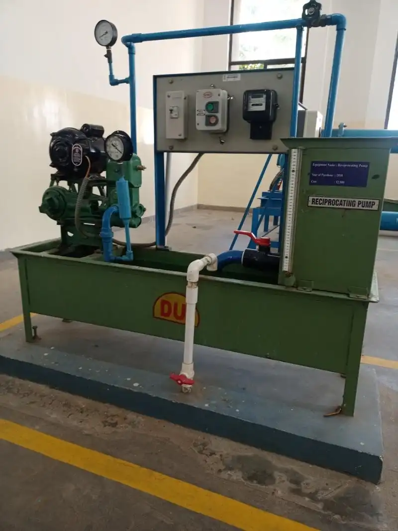
A reciprocating pump is a class of positive-displacement pumps that includes the piston pump, plunger pump, and diaphragm pump. Well maintained, reciprocating pumps can last for decades. It is often used where a relatively small quantity of liquid is to be handled and where delivery pressure is quite large. In reciprocating pumps, the chamber that traps the liquid is a stationary cylinder that contains a piston or plunger.
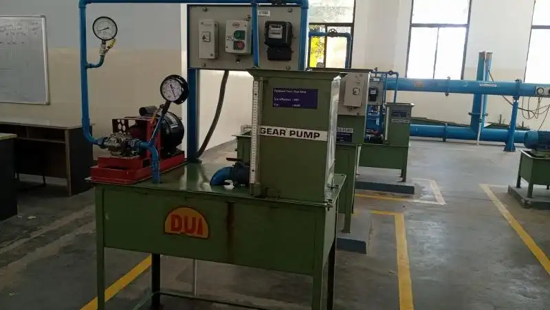
A gear pump uses the meshing of gears to pump fluid by displacement. They are one of the most common types of pumps for hydraulic fluid power applications. Gear pumps are also widely used in chemical installations to pump high viscosity fluids. There are two main variations: external gear pumps which use two external spur gears, and internal gear pumps which use an external and an internal spur gear (internal spur gear teeth face inwards, see below). Gear pumps are positive displacement (or fixed displacement), meaning they pump a constant amount of fluid for each revolution. Some gear pumps are designed to function as either a motor or a pump.
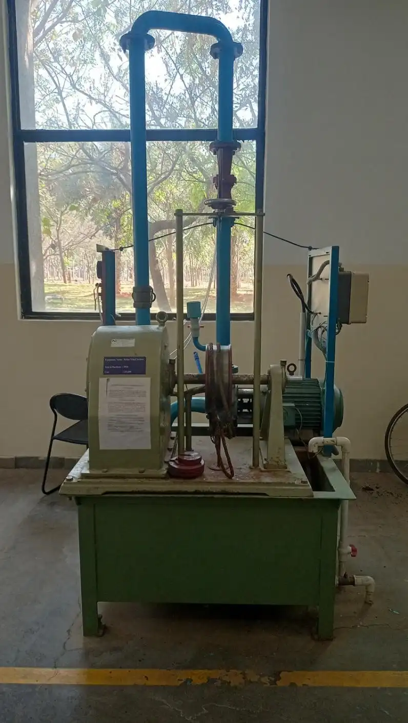
The Pelton wheel or Pelton Turbine is an impulse-type water turbine. The Pelton wheel extracts energy from the impulse of moving water, as opposed to water's dead weight like the traditional overshot water wheel. Many earlier variations of impulse turbines existed, but they were less efficient than Pelton's design. Water leaving those wheels typically still had high speed, carrying away much of the dynamic energy brought to the wheels. Pelton's paddle geometry was designed so that when the rim ran at half the speed of the water jet, the water left the wheel with very little speed; thus this design extracted almost all of the water's impulse energy—which made for a very efficient turbine.
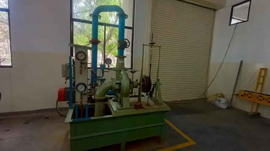
The Francis turbine is a type of water turbine. It is an inward-flow reaction turbine that combines radial and axial flow concepts. Francis turbines are the most common water turbine in use today, and can achieve over 95% efficiency. Francis turbines are primarily used for producing electricity. The power output of the electric generators generally ranges from just a few kilowatts up to 1000 MW, though mini-hydro installations may be lower. The best performance is seen when the head height is between 100–300m (330–980 ft). Penstock diameters are between 1 and 10 m (3.3 and 32.8 ft). The speeds of different turbine units range from 70 to 1000 rpm. A wicket gate around the outside of the turbine's rotating runner controls the rate of water flow through the turbine for different power production rates. Francis turbines are usually mounted with a vertical shaft, to isolate water from the generator. This also facilitates installation and maintenance.
The Kaplan turbine is a propeller-type water turbine which has adjustable blades. It was developed in 1913 by Austrian professor Viktor Kaplan, who combined automatically adjusted propeller blades with automatically adjusted wicket gates to achieve efficiency over a wide range of flow and water level. The Kaplan turbine was an evolution of the Francis turbine. Its invention allowed efficient power production in low-head applications which was not possible with Francis turbines. The head ranges from 10 to 70 metres (33 to 230 ft) and the output ranges from 5 to 200 MW. Runner diameters are between 2 and 11 metres (6 ft 7 in and 36 ft 1 in). Turbines rotate at a constant rate, which varies from facility to facility. That rate ranges from as low as 54.5 rpm (Albeni Falls Dam) to 450 rpm. Kaplan turbines are now widely used throughout the world in high-flow, low-head power production.
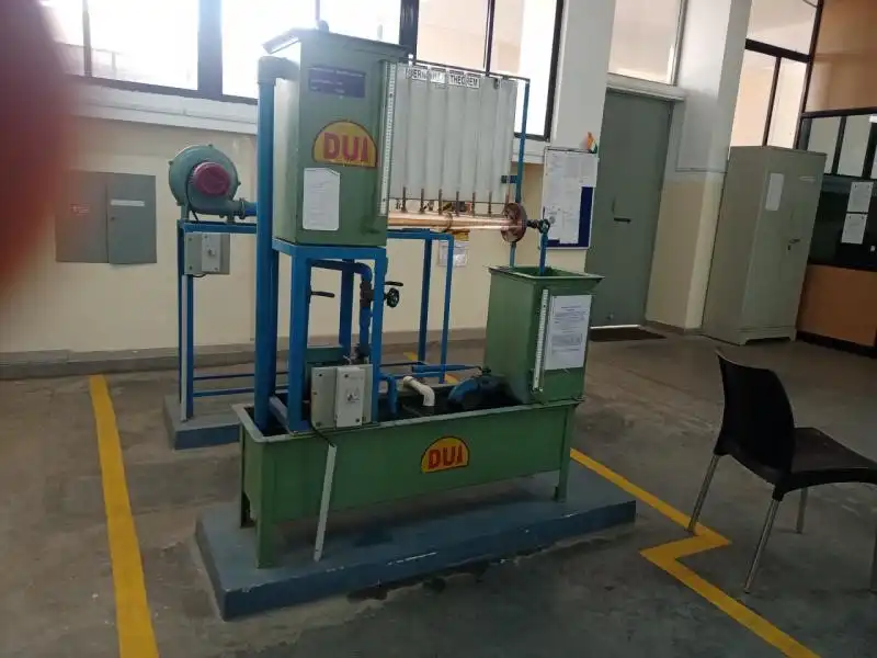
Energy presents in the form of pressure, velocity, and elevation in fluids with no energy exchange due to viscous dissipation, heat transfer, or shaft work (pump or some other device). The relationship among these three forms of energy was first stated by Daniel Bernoulli (1700-1782), based upon the conservation of energy principle. Bernoulli’s theorem pertaining to a flow streamline is based on three assumptions: steady flow, incompressible fluid, and no losses from the fluid friction. The validity of Bernoulli’s equation will be examined in this experiment.
.webp)
A pontoon is allowed to float in a small tank having a transparent side. Removable steel strip is placed in the model for the purpose of changing the weight of the model. Displacement of weight is measured with the help of a scale. By means of a pendulum (consisting of a weight suspended to a long pointer) the angle of tilt can be measured on a graduated arc. For tilting the ship model, a cross bar with two movable hangers is fixed on the model. Pendulum and graduated arc are suitably fixed at the center of the cross bar. A set of weights is supplied with the apparatus.
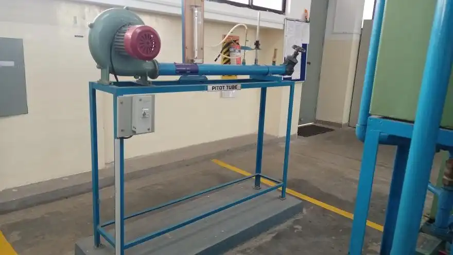
A pitot measures fluid flow velocity. It was invented by a French engineer, Henri Pitot, in the early 18th century and was modified to its modern form in the mid-19th century by a French scientist, Henry Darcy. It is widely used to determine the airspeed of aircraft; Water speed of boats; and the flow velocity of liquids, air, and gases in industry.
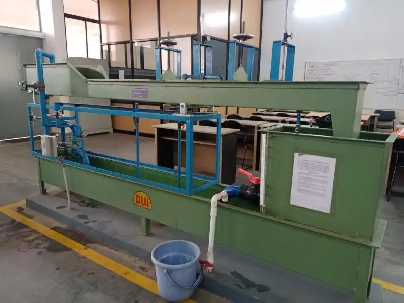
In fluidmechanics and hydraulics, open-channel flow is a type of liquid flow within a conduit with a free surface, known as a channel. The other type of flow within a conduit is pipe flow. These two types of flow are similar in many ways but differ in one important respect: open-channel flow has a free surface, whereas pipe flow does not.
.webp)
An orifice is an opening, of any size or shape, in a pipe or at the bottom or side wall of a container (water tank, reservoir, etc.), through which fluid is discharged. If the geometric properties of the orifice and the inherent properties of the fluid are known, the orifice can be used to measure flow rates
A mouthpiece is a short tube fitted to a same size circular opening provided in a tank so that fluid may flow through it. Orifice and mouthpiece are used to measure the rate of flow of liquid. The apparatus is designed to measure the co-efficient of discharge of orifice and mouthpiece.
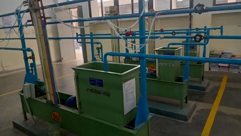
The energy required to push water through a pipeline is dissipated as friction pressure loss, in m. “Major” losses occur due to friction within a pipe, and “minor” losses occur at a change of section, valve, bend or other interruption. In this practical you will investigate the impact of major and minor losses on water flow in pipes.
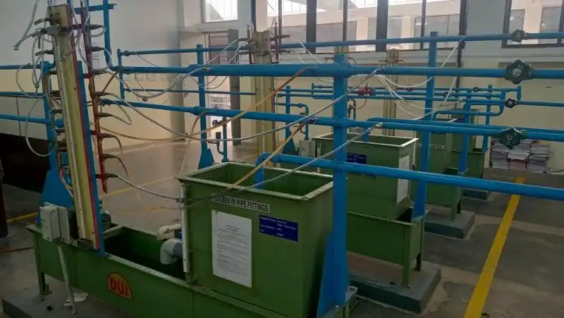
Minor losses in pipe flow are a major part in calculating the flow, pressure, or energy reduction in piping systems. Liquid moving through pipes carries momentum and energy due to the forces acting upon it such as pressure and gravity. Just as certain aspects of the system can increase the fluids energy, there are components of the system that act against the fluid and reduce its energy, velocity, or momentum. Friction and minor losses in pipes are major contributing factors.